Positive Negative Leads on Power Supply Have Contempt Continuity
Now we know the reason. About Polarity Test,You all know that inDirect Current or DC, there is a negative terminal and a positive terminal. Here, the charges move from the positive side to the negative side, and thus battery produces an electric current. This negative and positive of terminals is known aselectricalpolarity.
However, inAlternating Current or AC, there are no negative and positive terminals. The current direction alternates between the two poles. Therefore, we have to confirm the terminals before connecting any device. You can determine it by doing a simple polarity test; otherwise, there is a risk of having a short circuit or electric shock.
What is a Polarity Test?
In AC supply, you have to test the polarities to make sure the device has a connection withthe phase conductor .This test confirms that the electrician has connected the line conductor and neutral conductor to the terminal of the device, where it should be.
For instance, while connecting around the Edison-screw lamp holder, you have to connect the line to the central terminal and neutral to the outer terminal. You have to break the circuit and place your digital meter in series to the device and source to check this. If, upon turning on, you see any changes in the meter, the connection is correct. Else circuit is dead.
What are the Polarity Testing Methods?
You can perform one or multiple methods from the following to check the polarity of your apparatus.
Testing by visual inspection
The very first test that you can conduct for checking polarity is by using your sight and memory. If you are an expert electrician or have hired one, the chances are that you don't need any fancy equipment for the inspection.
Using the IEC color scheme for wiring ,you can check the polarity without effort while installing the system. This knowledge comes very handy when you have no time to test it formally.
Testing by Resistance Values
You can also test the polarities of both poles by finding the resistance values. You have to check the resistance for both poles. If the neutral side has less value than the live site, it will quickly provide a pathway to excess current in a short circuit. If not, you have to revise the course.
Testing by Continuity
For this, you need a low resistance ohmmeter that can detect the slightest passing of current. For continuity test, you can go for the following procedure:
- Cut off the supply of power by closing the circuit breaker.
- Place a temporary link between the line and circuit protective conductor (CPC) or any other potential conductor.
- Place the probes on the line point and CPC point to conduct the continuity test.
- If the ohmmeters show 0 reading with a beep, then there is no problem with the circuit, and it is not broken.
- However, the ohmmeter may show any ohmic value on the screen. In that case, there are chances for a broken or faulty circuit system. You can resolve it by changing the connections or the defective part of this circuit.
Live Testing by a Multimeter
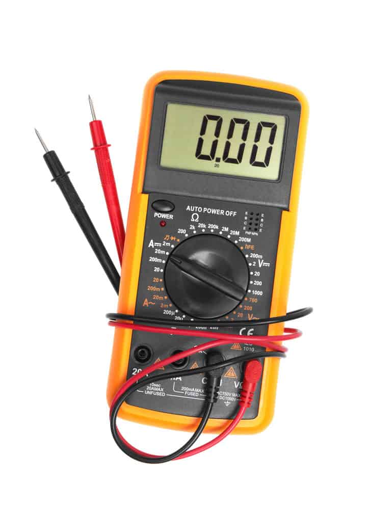
A digital multimeter is a device that checks voltage between two poles. Usually, a multimeter has a black and red probe for neutral or line, respectively. As it is a multimeter, you have to set it to "Voltmeter" mode first and then take your reading.

You can follow these simple steps.
- Take the probes of the multimeter.
- Insert the red probe into the outlet opening, which has a live 120V connection. Insert the black one into 0V neutral conductor connection. If the readings appear on the screen indicating full voltage, the system is excellent.
- Now, insert the red probe into the outlet opening, which has a live 120V connection. Insert the black one into the 0V ground connection. If the readings appear on the screen indicating full voltage again, there is no problem.
- Similarly, insert the red probe into the outlet opening, which has a 0V ground connection. Insert the black one into 0V neutral terminal. If no reading appears on the screen, it is appropriately connected. Otherwise, it would help if you revised the wiring.
Polarity Test for Important Systems
Now that you know the techniques for testing the polarity in the sockets all over your home. Yet, it might not be applicable in more advanced circuitries. You have to perform different methods that are specific to a device. You will look into some practical procedures as below.
Polarity Test of Speaker

You cannot notice one speaker, but if a pair has inverted polarity, it can cause significant changes in the upcoming sound, even silence. Hence, you need to check each wiring so that you don't overlook the wrong one. You can inspect it by.
- Watching out for speaker wire labels: If there is a + or – symbol on the terminals, connect the wires using them. Link the + or red terminal of amplifier to + terminal of the speaker and Black or – terminal of amplifier to – of the speaker.
- Using a Speaker Tester: This relatively inexpensive investment can be your lifetime aid if you love using the speaker. A digital meter type of device lets you determine the poles just like you measure the voltage, without any attached amplifier.
- Using Smartphone App: There are many apps available on the apple store or play store that you can use for a quick check-up on polarity. You need to connect your phone with a speaker. The app will send the sound signals to the speaker, catch them and then measure the polarity change, if any.
- Using a 9V Battery: You can also connect the speaker directly to a 9V DC supply. If the speaker moves inwards, you have opposite terminals connected. Else speaker is okay.
Polarity Test of Transformer

There are two types of polarities in the secondary winding and primary winding.
Additive polarity, where you have to add the values of both primary voltage (Va) and secondary voltage (Vb), add them, and you get the total voltage (Vc) between them.
Vc = Va + Vb
Subtractive polarity, where you have to subtract the values of both primary voltage (Va) and secondary voltage (Vb), add them, and you get the voltage (Vc) between them.
Vc = Va – Vb
If Vc = Va – Vb, it is a step-down transformer, and if Vc = Vb – Va, it is a step-up transformer.
You can check for additive polarity and subtractive polarity by performing these steps.
- Connect the primary winding with voltmeter Va and secondary winding with voltmeter Vb.
- Connect another voltmeter (Vc) across the secondary and primary winding.
- Now, apply some voltage to the primary winding. If the value of Vc is the sum of Va and Vb, then it is additive polarity. If it is showing the difference, then Vc is subtractive polarity.
Polarity Test of Lighting Circuit
With time, it is vital to check the polarity of lightning circuits in our homes, even if you haven't changed the circuitry in a while. You can perform your inspection by using a megger meter for accurate ratings.

Connect one probe to the live terminal and the other with the bulb while keeping the switch OFF. Check for the deflection value. It shows high resistance. If the switch is ON, resistance will drop to a lower value. It shows the circuit has correct polarities. If things go the other way round, there is a mistake in connecting the circuit.
Polarity Test of Induction Motor
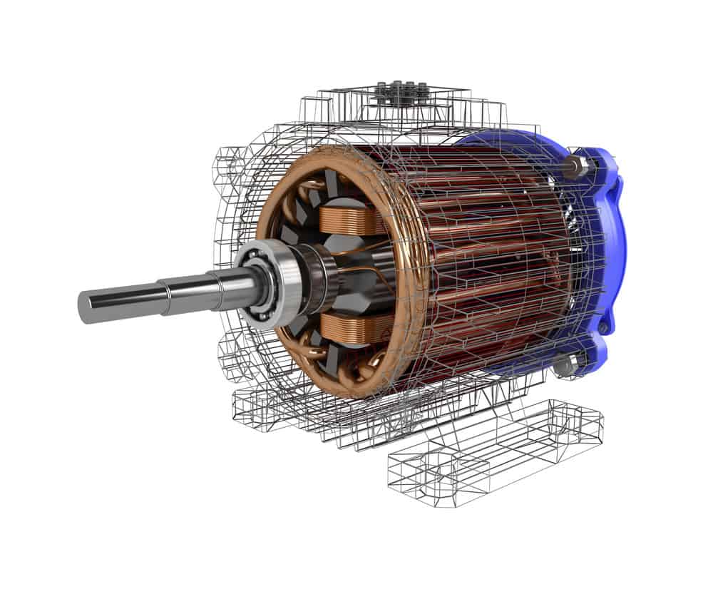
Before installing a new induction motor, you need to determine the polarity readings of its terminals, or the wrong polarity may damage its windings. Also, the three-phase supply creates an uneven magnetic field across the coil. It makes the output torque pulsating in the entire device.

The terminals of an induction motor are marked as A1, A2; B1, B2; C1, C2. If their polarities are unknown, you need to locate them out by testing each terminal. You can test the terminals by using DC and AC supply separately.
Testing by AC Supply
- By using a multimeter, determine the continuity between random sets. If the continuity sound beeps, tag them as A1 and A2, B1 and B2, C1 and C2.
- Now, take two winding A and B. Connect the terminal A2 with B1 to be in series. Apply AC power supply to coil A and check the ratings across A1 and B2.
- If the voltage across A1 and B2 is less than the applied voltmeter readings, then A1 and B1 have the same polarities. Otherwise, interchange A1 to A2. Repeat the same process for determining the polarity of other points.
Testing by DC Supply
- Again randomly pick the points as A1 and A2.
- Attach the positive terminal to A1 and the negative terminal to A2.
- Place another coil parallel to coil A, let's say coil B, and attach the galvanometer on its terminals.
- Close the switch of the DC supply and check the deflection in the meter. If it is positive or clockwise, the positive terminal is attached to + of the meter. The negative terminal is connected to the – side. It is vice versa for the other way round.
- Repeat the same process for Coil C and determine its polarities.
Conclusion
You may encounter multiple incidents when wiring across the house and circuit breakers fuse after a while. That's a wrong connection that has caused an excess flow of current across the circuit. Thus, you have to test polarities in all the switches, so their links are in phase conductor only.
By the way, here at Cloom, we offer custom wiring harnesses with attention to each detail so that your devices are safe from any harmful consequences. Contact our team and book your service now.
richardsonnourn1986.blogspot.com
Source: https://www.wiringo.com/polarity-test.html
0 Response to "Positive Negative Leads on Power Supply Have Contempt Continuity"
Post a Comment